

Bob’s Imaging Fundamentals #10: Morphology Part 1
The basics of Erosion
If you look up ‘Morphology’ in the dictionary, you are likely to find the following definition: “study of forms of animals and plants or of words”. In Image Processing, Morphology refers to mathematical morphology, which is built on the foundations of set theory. Don’t worry though; I have no intentions of going into a long drawn out discussion of set theory instead, I will only show you what we need to understand the foundations of Binary Morphology as it relates to Image Processing.
Let’s start by getting the boring stuff out of the way. The basic building blocks of Binary Morphology are the logical AND and logical OR operations:

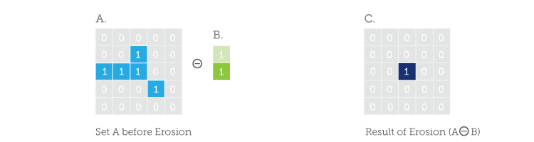
The other basic tool of Binary Morphology is the convolution. Well, technically, it’s not really convolution because Morphology is based on ‘set’ operations like ‘AND’ and ‘OR’ whereas convolution is based on mathematical operations like multiplication, addition and division. What’s more, in Morphology we don’t use a ‘Kernel’ to zip around the image and process pixels, we use a ‘Structuring Element’. But enough with the preliminaries, let’s look at an example of two ‘sets’ of 1’s and 0’s. Set ‘A’ is like a small binary image (binary, meaning all the pixels in the image are either 1 or 0) and, set ‘B’ will be our structuring element:
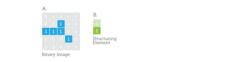
In Set B, the dark green is used to indicate the ‘origin’ of our structuring element. A darker shade of colour will indicate which pixel is being processed at any given time.
The Morphological operator we are going to talk about today is called Erosion. The Erosion operation gives you a positive result if all the points of your structuring element are contained in the target set. In other words, we ‘AND’ all the elements of B with all the equivalent elements at your current position in A, if the result is 1’s everywhere, you put a ‘1’ at the current position in the output image. Now, I know that explanation sucks, so let’s do an example. Let’s say we want to process the darker blue pixel in A.
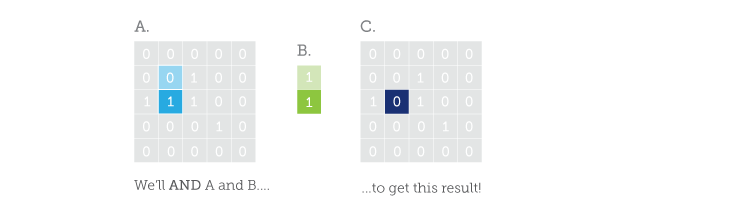
If we compare the contents of B to the blue portions of A, we see that their lower elements match, but the upper ones do not. So, we ‘AND’ the elements of B with the equivalent elements of A at our current position. Then we ‘AND’ all the results of this first ‘AND’ and the resulting ‘AND’ is stored at the position of B’s origin in the result set ‘C’. Get it? I didn’t think so… Here is another illustration:
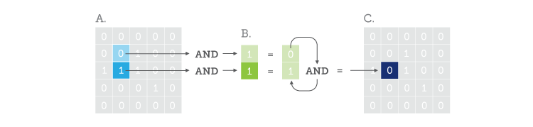
So, we end up with a ‘0’ at our current position in the result set ‘C’ (Note: I have changed the colour of the result so as not to confuse an already confusing discourse).
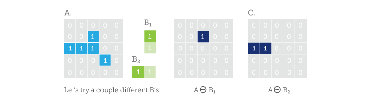
If we move B one pixel to the right in A and repeat the operation, we see that both the underlying elements in A match both the elements of B:
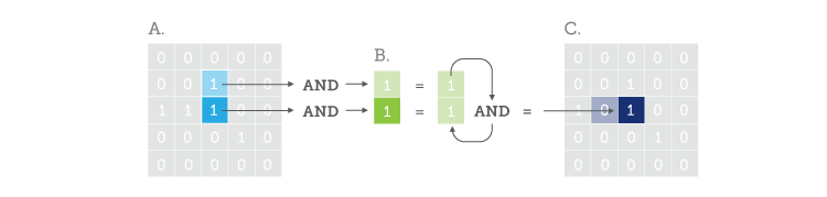
In this case, we end up with a ‘1’ at our new position in the result set. Finally, if we keep going through the rest of A we will find that there is no other position where we match all the elements of B, thus the final result of the erosion of A by B will look like C:
As you can see in C, set A gets ‘eroded’ down to a single element by set B (By the way, the funny little circle with the ‘-‘ in it is the universal symbol for Erosion; remember this, it may be useful some day). Obviously, the results would have changed had set B’s origin been on top or if set B had been horizontal:
To finish, let’s see what happens when we apply Binary Erosion to a real image using a 5 x 5 structuring element. (Note: In the original image below, a white pixel will be equivalent to a ‘1’ and a black pixel a ‘0’.)
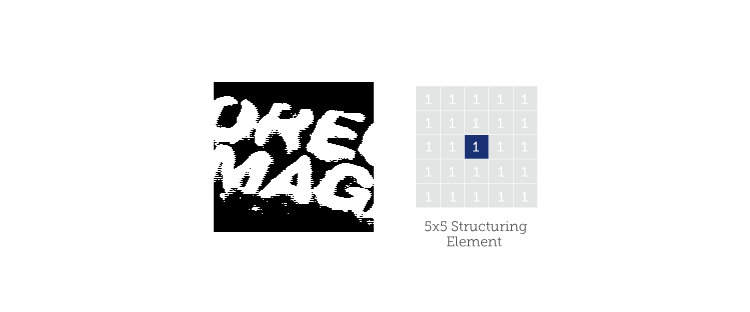
So what do we get when we run the 5 x 5 structuring element all over our binary image?
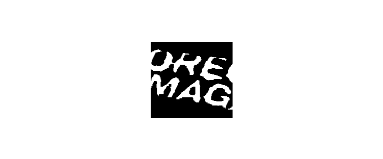
A cleaner image! That is the real beauty of it, since Erosion nibbles away part of the original object; it also gets rid of isolated noise. The bigger your structuring element, the bigger the noise you can get rid of. You can also change the shape of your structuring element in order to target noise with a specific shape. There are pitfalls though, notice how the edges have acquired a kind of ‘blockiness’? This is due to the square shape of our structuring element. Also, note how some of the tops of the letters have completely disappeared. This is due to the large size of the structuring element and my general inability to take a decent picture. However, in my defense I was wearing the pullover when I took that shot, and it gives us an interesting starting point for next time…
Next time, we are going to see another fundamental Morphological operator, which will help us repair some of the over-thinned bits in our Eroded image: ‘Dilation’.
About this article: Bob’s Imaging Fundamentals is an article series based on the work of Bob Howison. Originally titled Bob’s Brain Snacks, these articles were intended to help employees and partners get up to speed with the fundamental concepts of image processing. They became such a popular reference that we’ve decided to bring them to the Possibility Hub. As technology goes further, faster, and new industries discover the power of digital imaging, it’s important to remember the basics.
Bob’s Brain Snacks are recommended for anyone interested in learning about imaging technology. Sharpen your mind and try one!